I, ladies and gentlemen, am an idiot. I know this doesn't exactly come as a surprise to many of you. 
In this particular case, as has happened all too many times in the past, I got too focused on one "solution". Focused on trying to execute that one idea, I didn't bother thinking of other options.
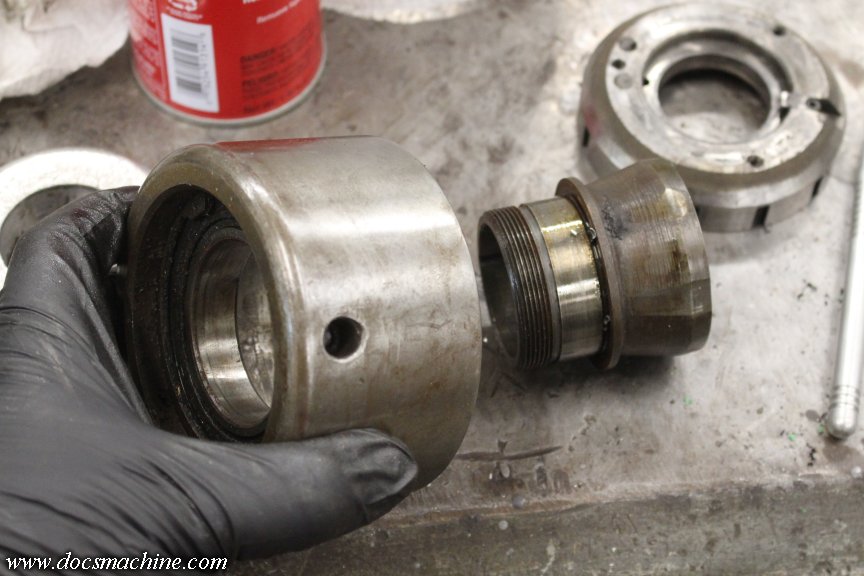
My problem was I needed a way to hold my parting tool further out than my basic tool post could. I had an extension, that didn't work. I had a different tool holder entirely- that turned out to be slightly too short, and oriented the tool in the wrong direction. I hit upon making an extended tool block to fit my existing tool post, and as already recorded for posterity, was stopped by a lack of suitable tooling.
This morning, in the sober light of noon or so, I realized that yes, indeed, I was an idiot. There was a way I could do it right and do it fast.
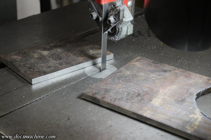
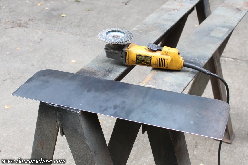
So, I went to my metal supplier, and bought 5" of 1-1/2" (38mm) square steel stock.
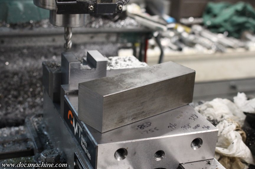
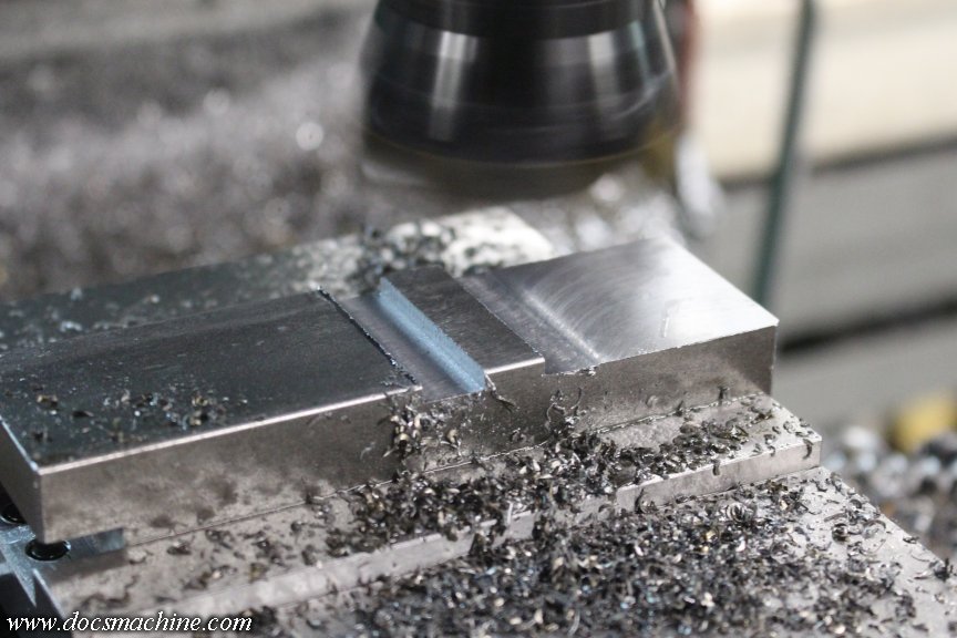
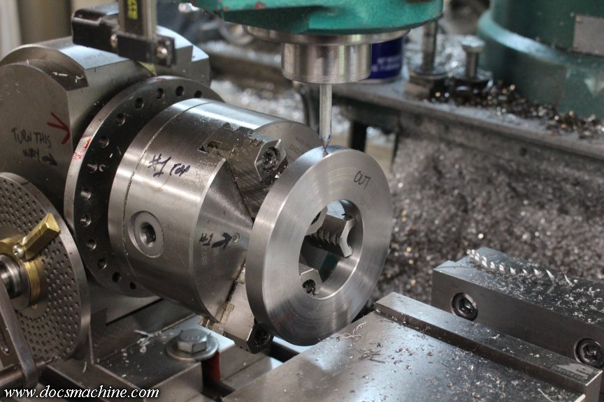
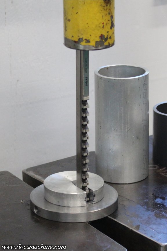
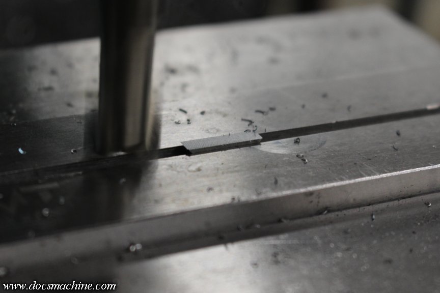
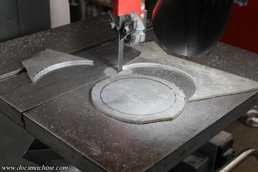
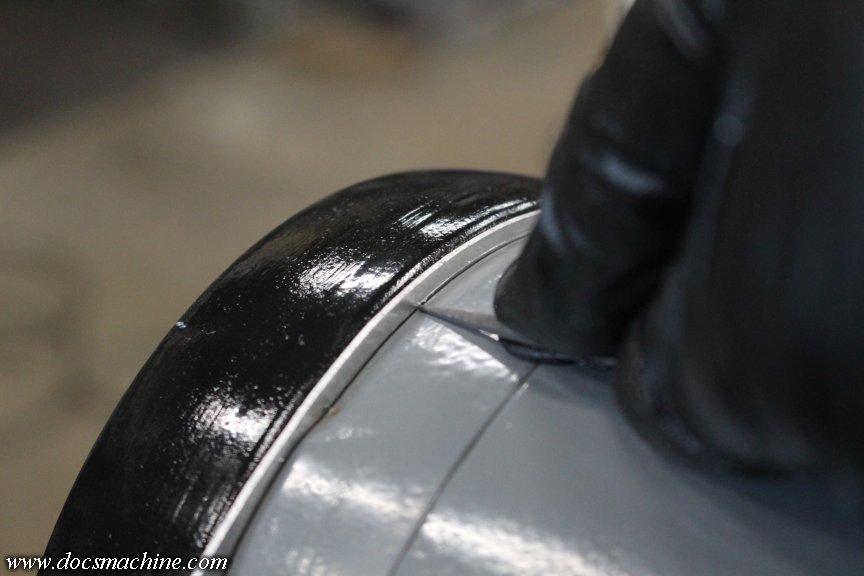
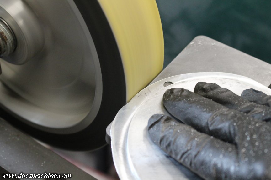
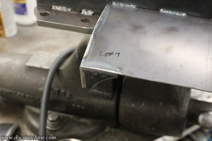
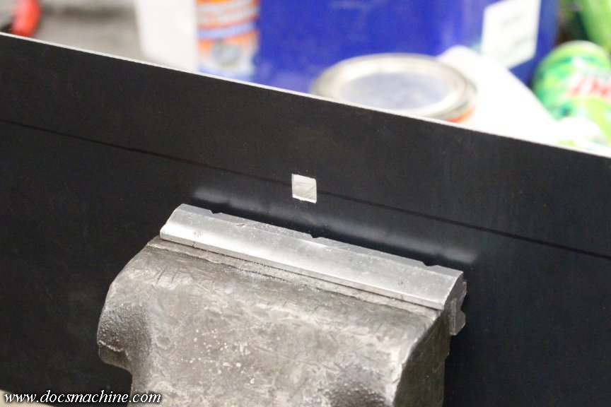
After a quick deburr in the belt grinder, I clamped it end up in the vise, and gingerly cut a 1/2" square notch in the end.
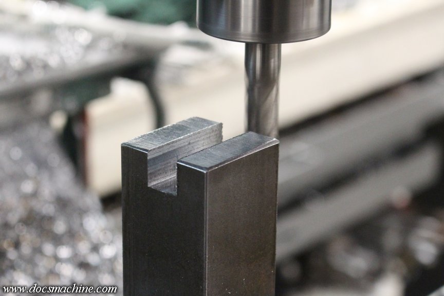
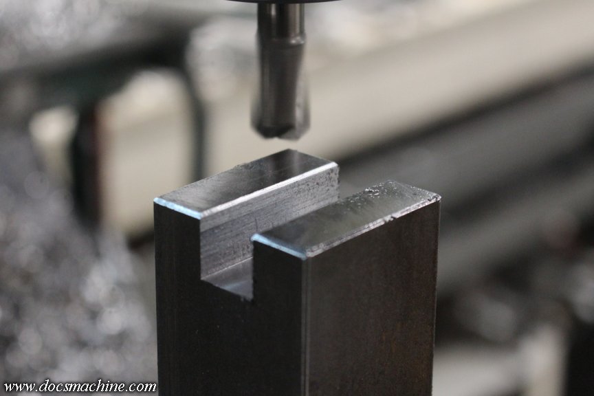
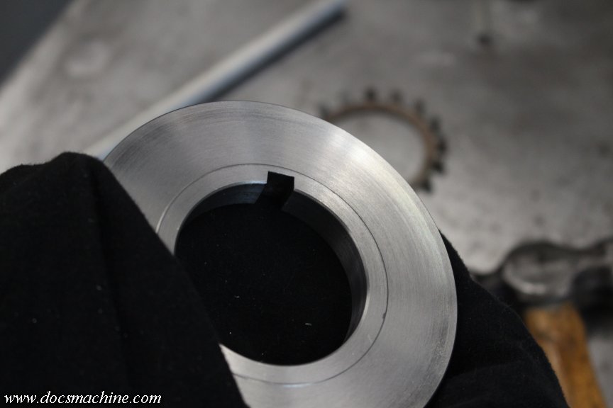
That got lightly chamfered for both looks and to reduce blood leakage...
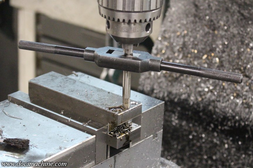
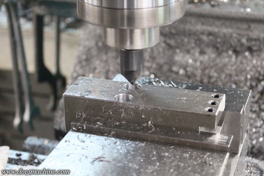
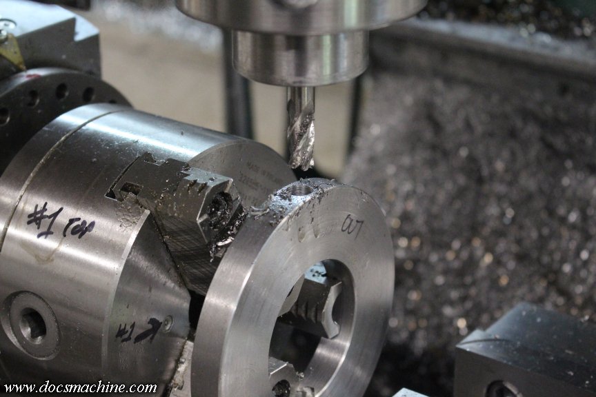
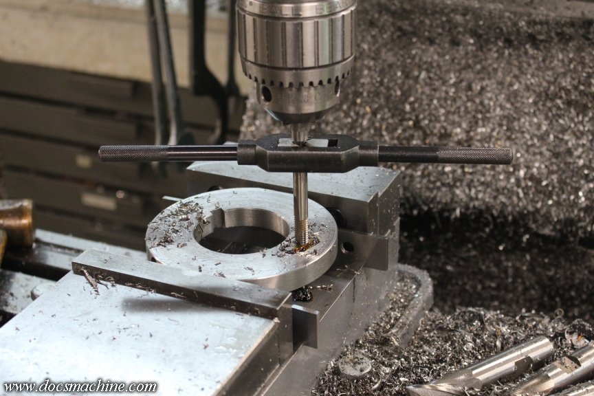
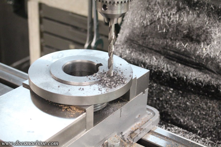
And then drilled and tapped for 5/16"-18:
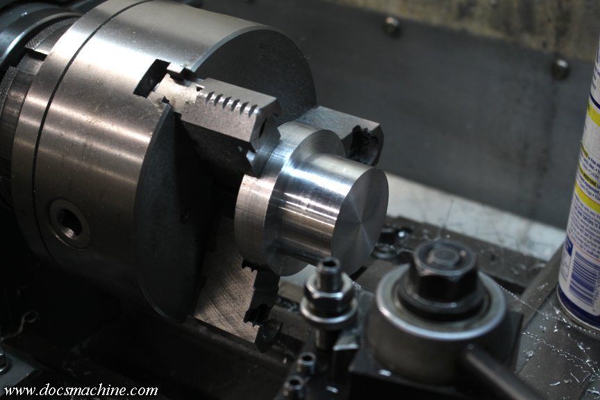
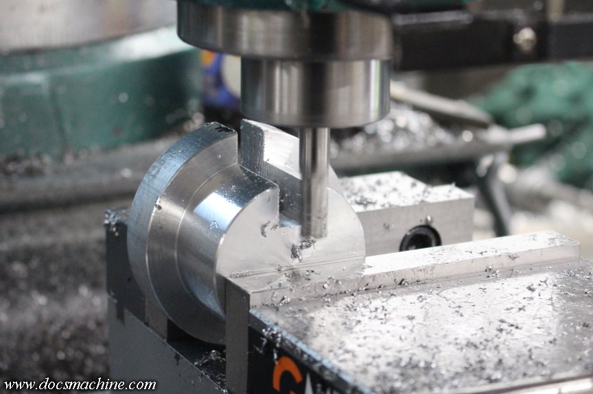
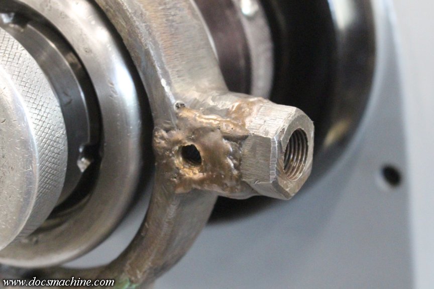
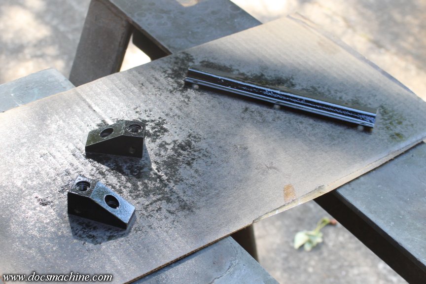
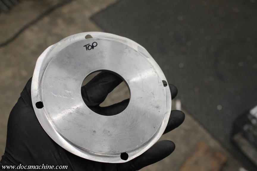
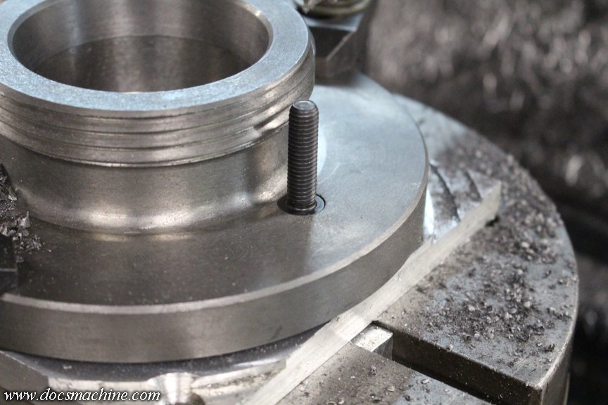
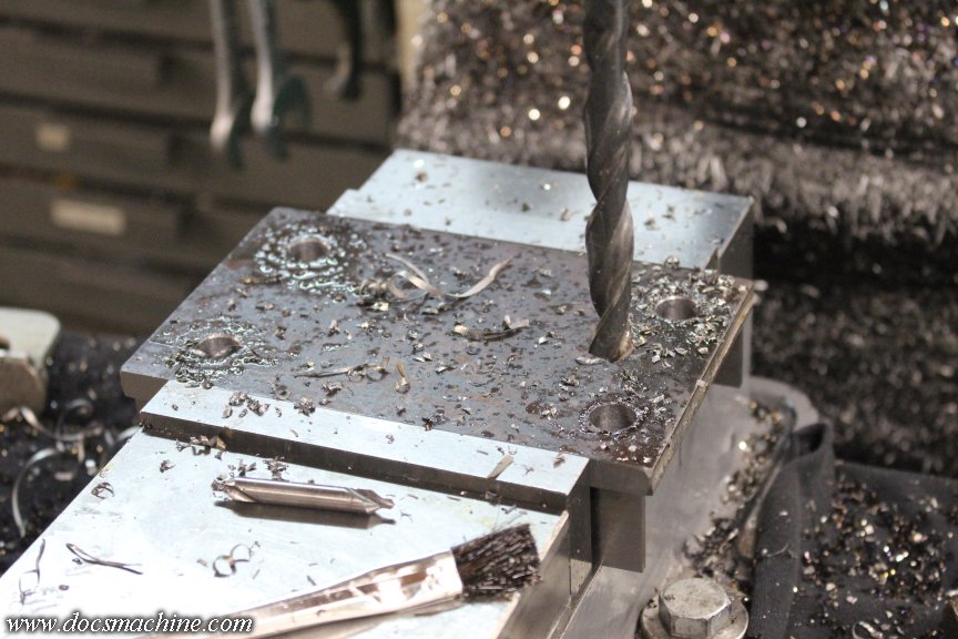
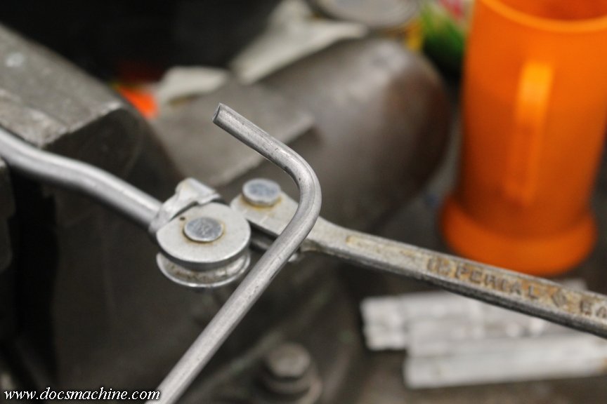
The soon-to-be underside got a notch and a flat to make a "key"....
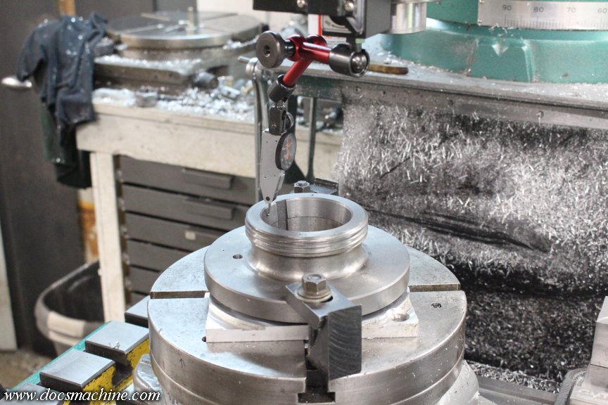
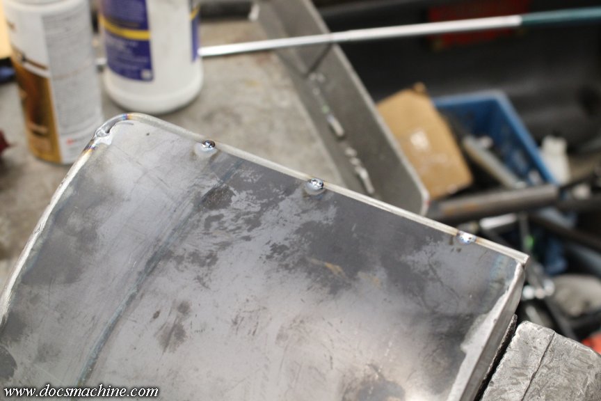
And then two carefully-measured and located bolt holes to mate up with the 'key' on the underside.
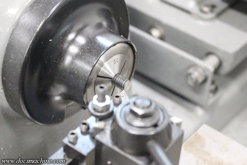
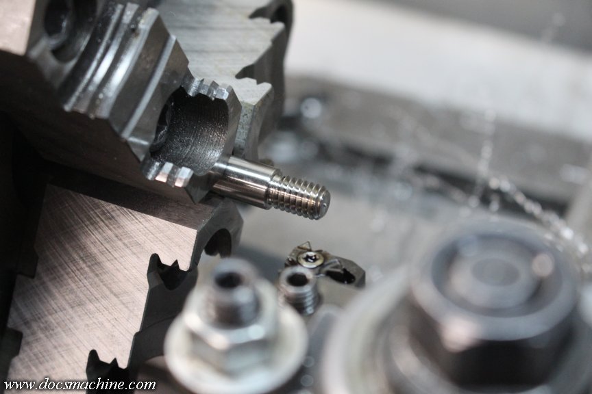
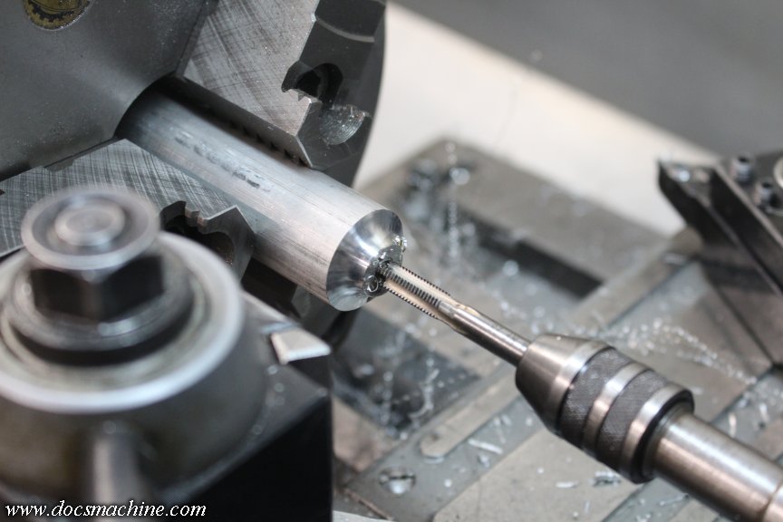
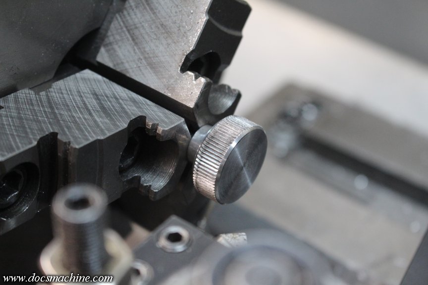
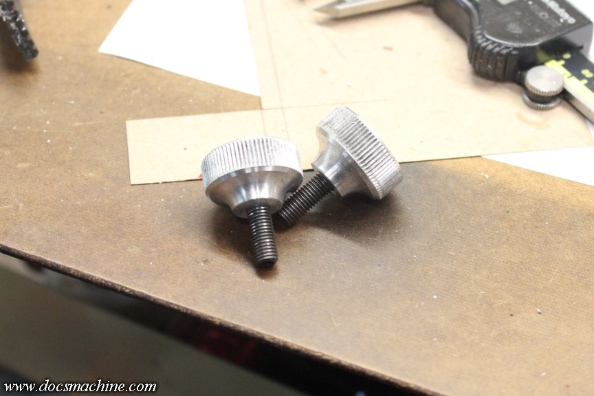
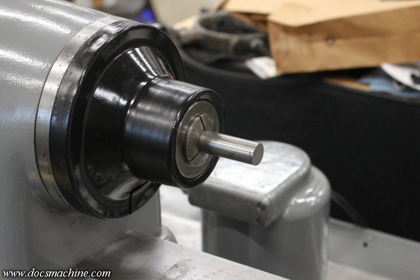
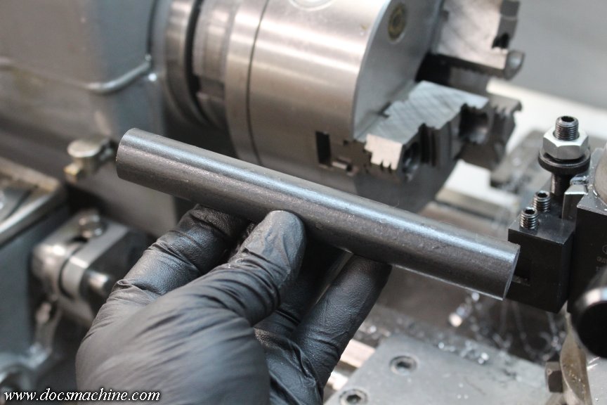
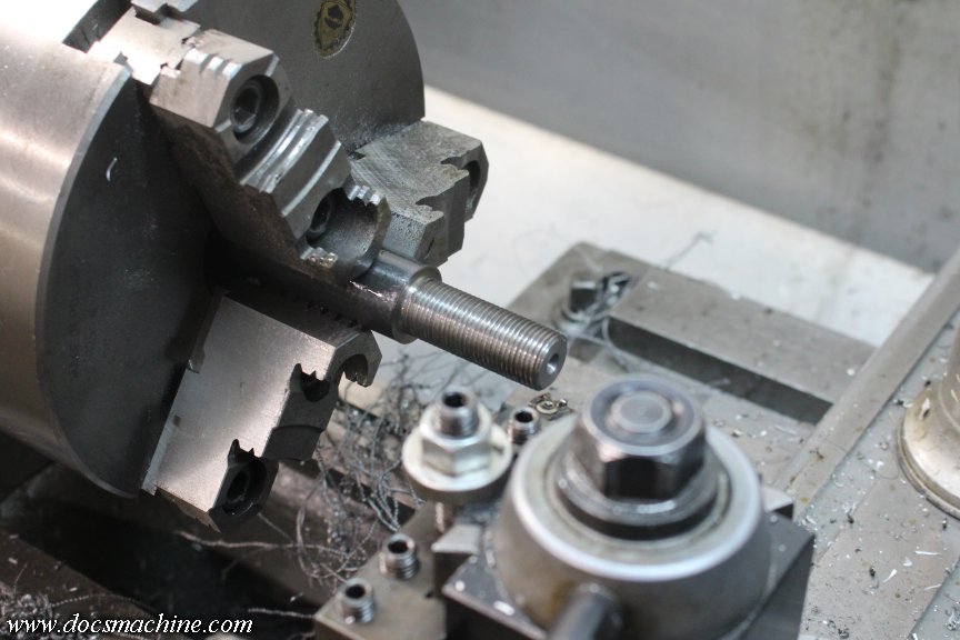
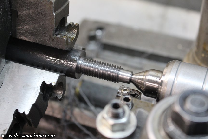
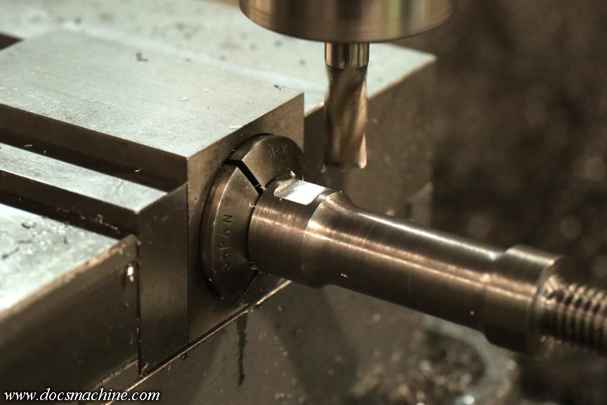
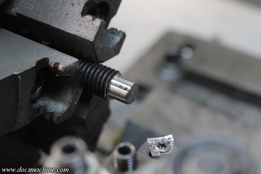
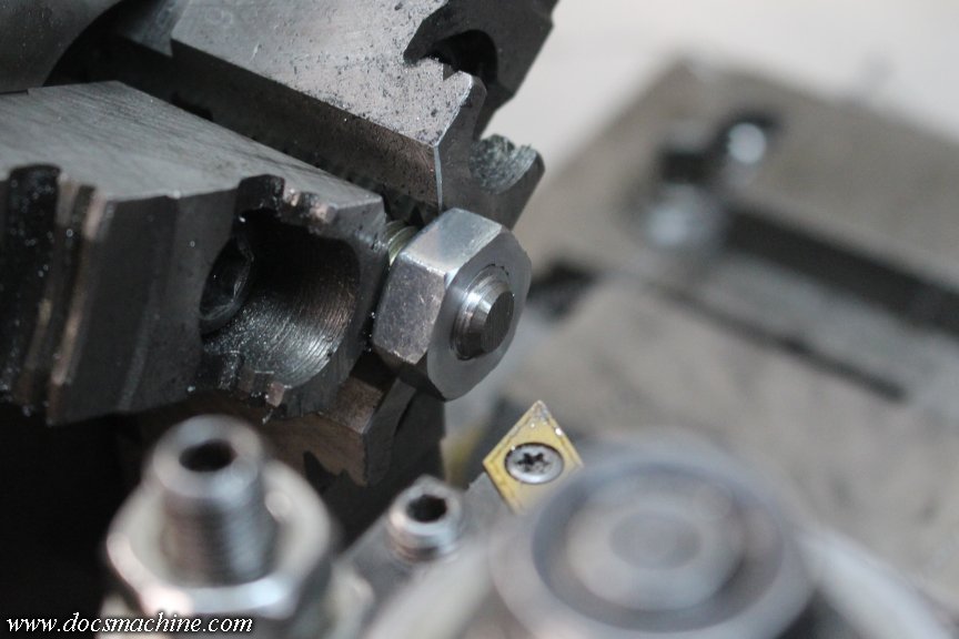
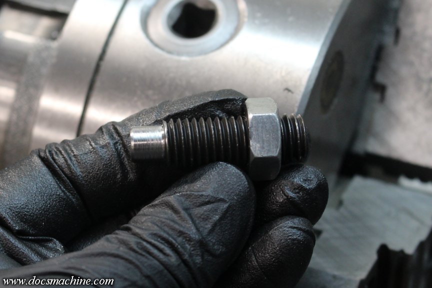
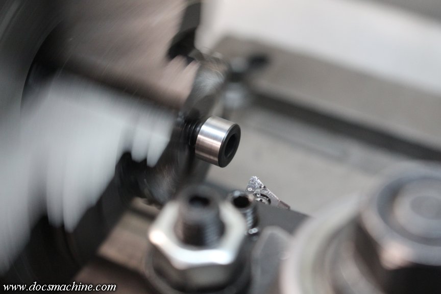
The bolts wound up just slightly long, so I threw a collet in the little Hardinge and shortened 'em up by about a sixteenth. (21 millifarthings.)
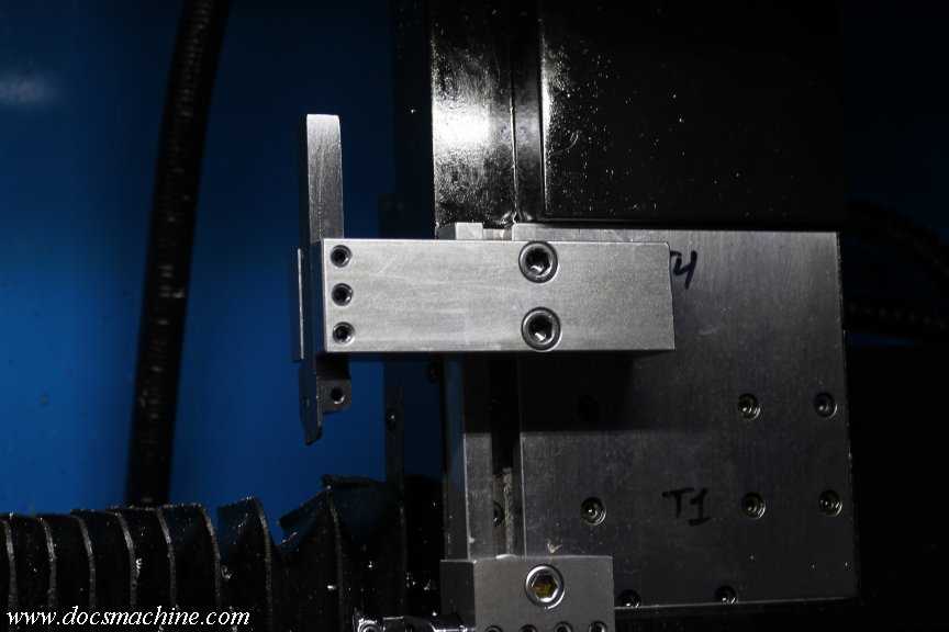
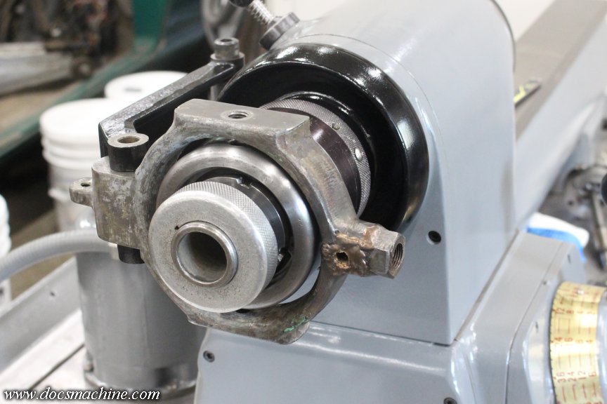
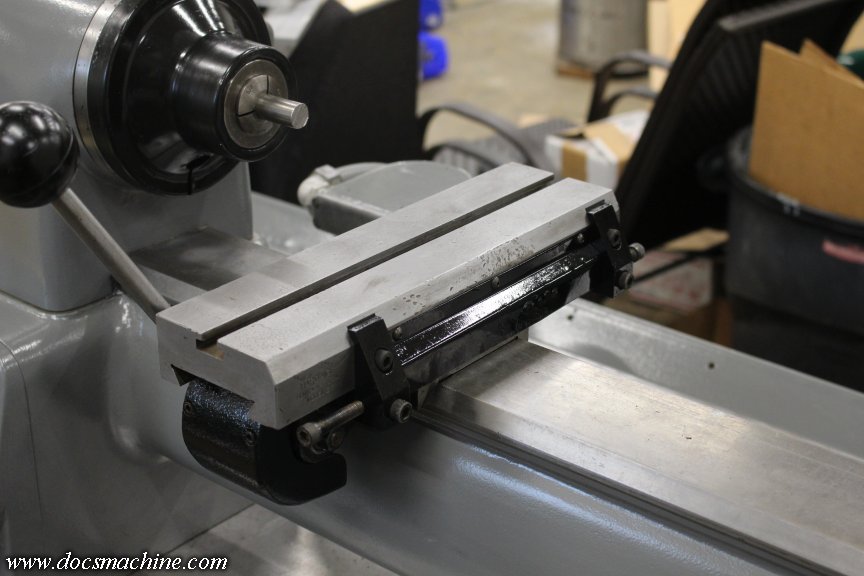
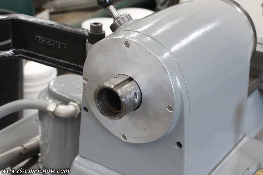
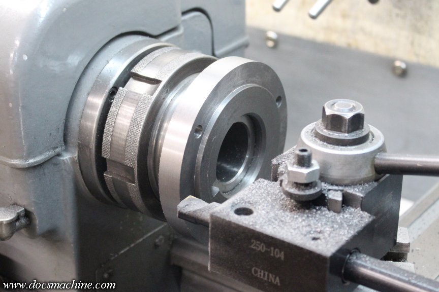
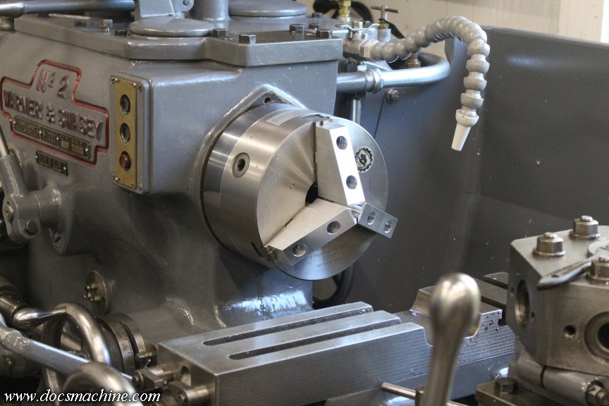
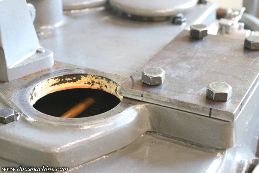
The whole thing bolts on, nice and solidly, like so:
Including the trip to the metal shop, the whole process took roughly three hours. (There was a lot of fiddling, fettling and fitting I didn't show. )
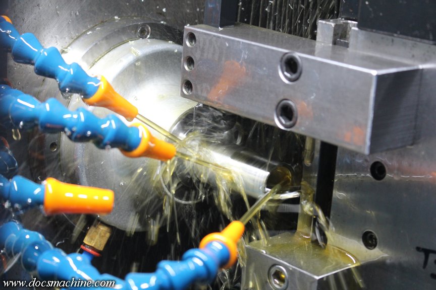
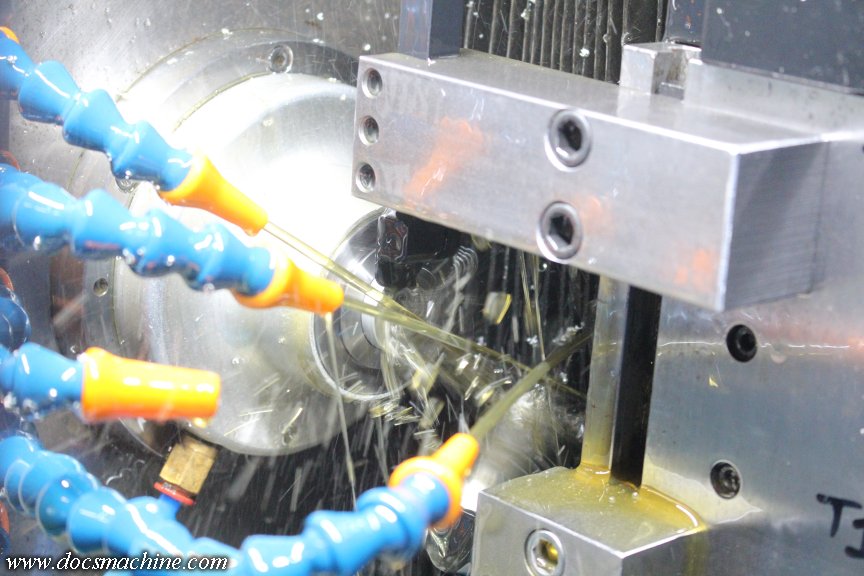
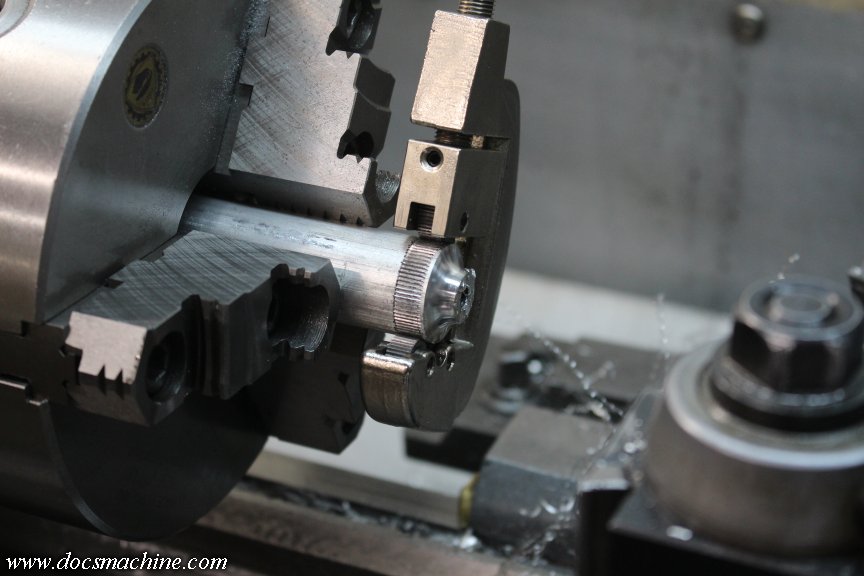
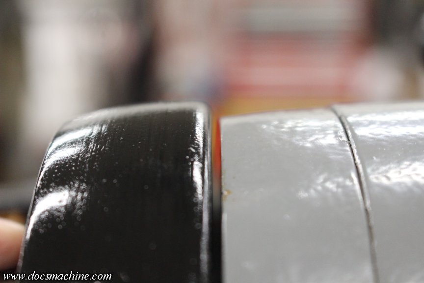
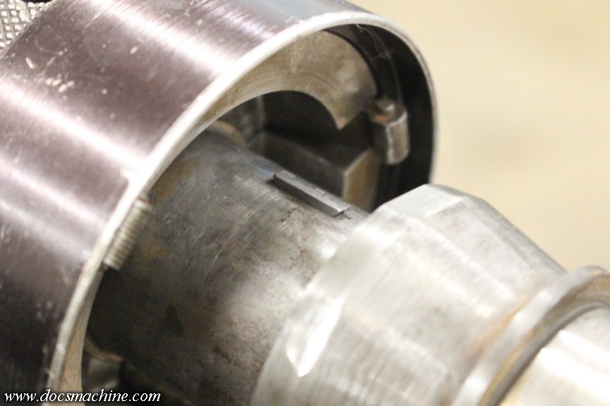
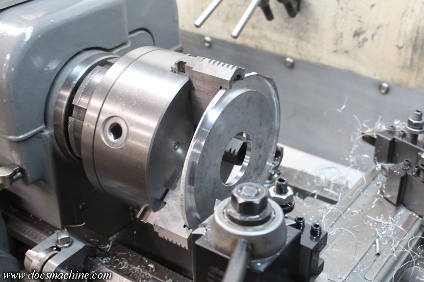
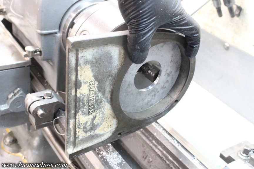
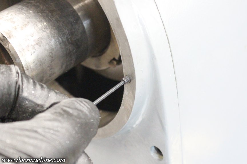
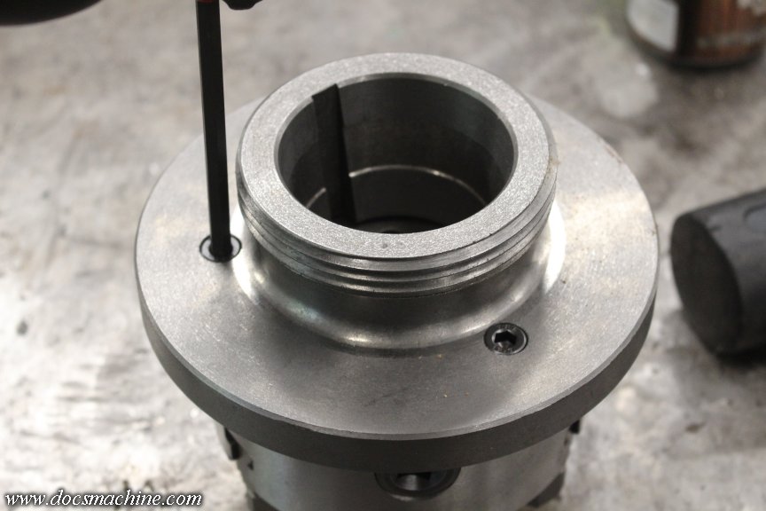
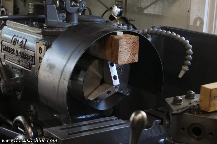
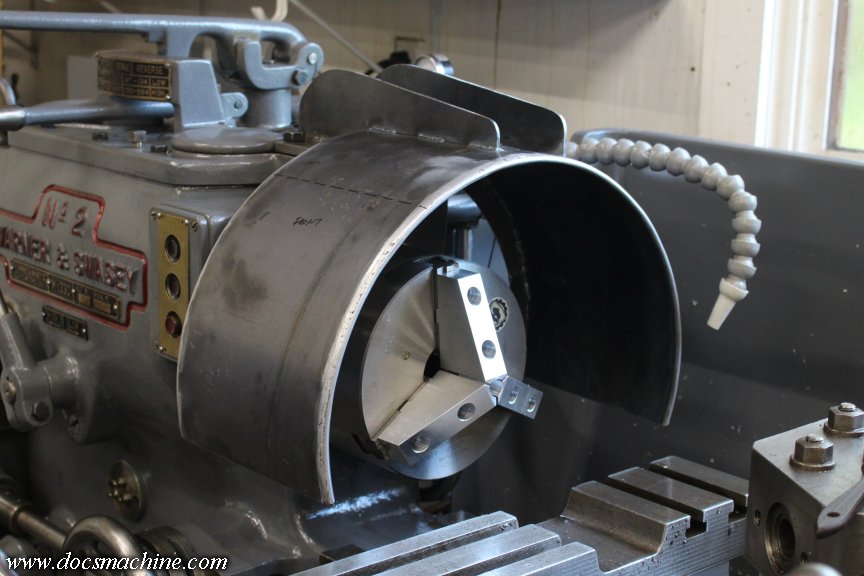
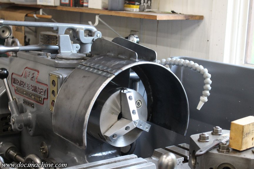
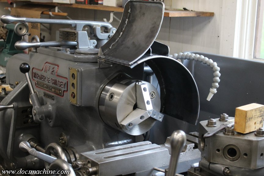
Anyway, I finished up programming the part, and took 'er for a spin:
You can see the "parted" piece falling towards the back, at the bottom center of the frame.
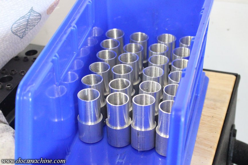
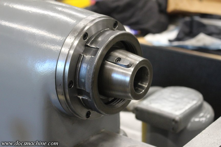
And, since I had the raw stock already cut and ready, I ran the first two pieces, for a total of 24 parts so far.
I'll be able to turn more over the rest of the week, which will put me- at least on this one task- three or four days ahead of where I'd be if I'd just waited for the cutter for the other block.
I'll still finish up the other block- it'll have its uses- but at least I can make a little quicker progress than I'd anticipated.
Doc.
In this particular case, as has happened all too many times in the past, I got too focused on one "solution". Focused on trying to execute that one idea, I didn't bother thinking of other options.
My problem was I needed a way to hold my parting tool further out than my basic tool post could. I had an extension, that didn't work. I had a different tool holder entirely- that turned out to be slightly too short, and oriented the tool in the wrong direction. I hit upon making an extended tool block to fit my existing tool post, and as already recorded for posterity, was stopped by a lack of suitable tooling.
This morning, in the sober light of noon or so, I realized that yes, indeed, I was an idiot. There was a way I could do it right and do it fast.
So, I went to my metal supplier, and bought 5" of 1-1/2" (38mm) square steel stock.
After a quick deburr in the belt grinder, I clamped it end up in the vise, and gingerly cut a 1/2" square notch in the end.
That got lightly chamfered for both looks and to reduce blood leakage...
And then drilled and tapped for 5/16"-18:
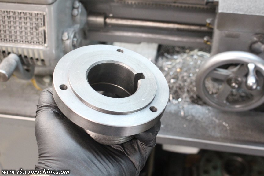
The soon-to-be underside got a notch and a flat to make a "key"....
And then two carefully-measured and located bolt holes to mate up with the 'key' on the underside.
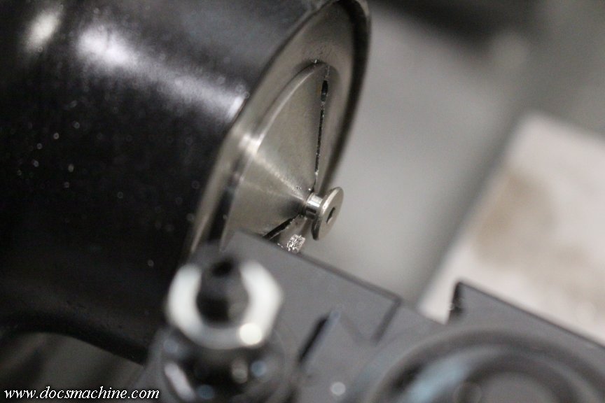
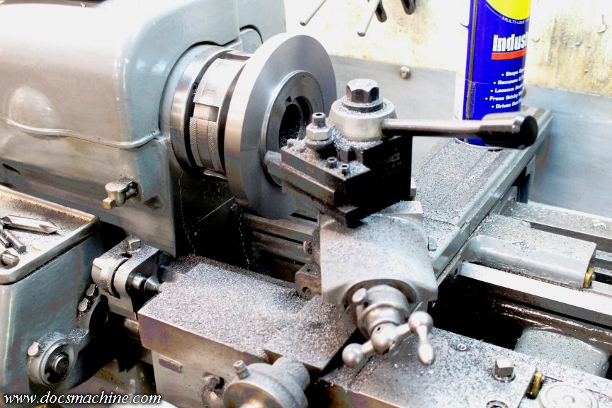
The bolts wound up just slightly long, so I threw a collet in the little Hardinge and shortened 'em up by about a sixteenth. (21 millifarthings.)
The whole thing bolts on, nice and solidly, like so:
Including the trip to the metal shop, the whole process took roughly three hours. (There was a lot of fiddling, fettling and fitting I didn't show.
)Anyway, I finished up programming the part, and took 'er for a spin:
You can see the "parted" piece falling towards the back, at the bottom center of the frame.
And, since I had the raw stock already cut and ready, I ran the first two pieces, for a total of 24 parts so far.
I'll be able to turn more over the rest of the week, which will put me- at least on this one task- three or four days ahead of where I'd be if I'd just waited for the cutter for the other block.
I'll still finish up the other block- it'll have its uses- but at least I can make a little quicker progress than I'd anticipated.
Doc.


Comment